


Brightfield Illumination with Spot and Bar Lights for Machine Vision
著者: Thomas Stard & Rebecca Charboneau
Introduction to Brightfield Illumination using Spot and Bar Lights
Brightfield lighting is one of the most commonly used machine vision illumination geometries. There are two types of brightfield illumination: full and partial brightfield. Full brightfield utilizes a diffuse light source like a ring light that is located directly above the object. Partial brightfield is typically produced by a spot, ring or bar light oriented anywhere from 90° to 45° from a sample (Figure 1). Compared to full brightfield, partial brightfield is the preferred technique for generating more contrast and enhancing surface features. The images below show different objects (diffuse and specular) with partial brightfield illumination using a white spot light or bar light. The images were taken with the 6mm C Series Fixed Focal Length Lens and 25mm C Series Fixed Focal Length Lens using the sensor IMX540 resized to a 2/3” sensor format for the C Series Fixed Focal Length Lenses.

Image Analysis and Evaluation of Brightfield Spot Light Illumination
| 6mm C Series Fixed Focal Length Lens | 25mm C Series Fixed Focal Length Lens |
|---|---|
A  |
A  |
B  |
B  |
C  |
C 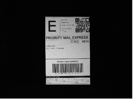 |
D 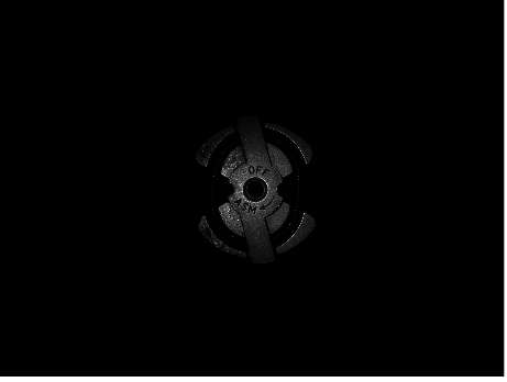 |
D 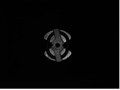 |
E 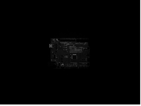 |
E  |
Table 1 features images taken with a spot light positioned for partial brightfield illumination. The angle of the spot light was varied from 90° - 45° depending on what object was being imaged to ensure limited hotspots and shadows. The images in the left column above were captured using the 6mm C Series Fixed Focal Length Lens at a working distance of 200mm while the images in the right column were taken with the 25mm C Series Fixed Focal Length Lens at a working distance of 750mm. The greater working distance of the 25mm C Series Fixed Focal Length Lens makes spot light positioning easier as the camera does not get in the way.
When imaging reflective objects like the printed circuit board (PCB, Panel E) or metal objects (Panel D), an incorrectly angled spot light can cause hotspots, making features like engravings, scratches, or circuitry difficult to detect. On the other hand, when imaging diffuse objects like the shipping label, this type of lighting geometry is ideal for applications like optical character recognition (OCR) to create high contrast. Although items with a glossy finish like the cap (Panel B) and medicine vial (Panel A) can have issues with hotspots, the partial brightfield illumination creates good contrast on the topographic features of the cap.
Image Analysis and Evaluation of Brightfield Bar Light Illumination
| 6mm C Series Fixed Focal Length Lens | 25mm C Series Fixed Focal Length Lens |
|---|---|
A  |
A  |
B  |
B 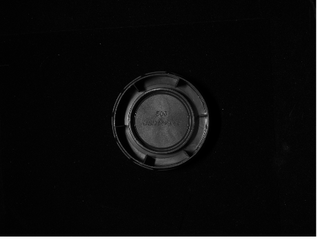 |
C 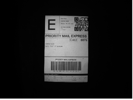 |
C  |
D  |
D 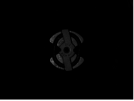 |
E 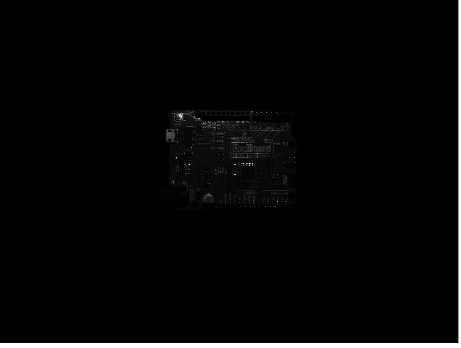 |
E  |
The images in Table 2 were taken with the same camera and lens setup as before, except that a bar light was used to produce the partial brightfield illumination. The illumination effect of the bar light is similar to the spot light, as seen in the similarity of the above images with the previous images taken with the spot light. The wide shape of the bar light makes it easier to light larger objects like the label (Panel C). However, it also makes it more challenging to image reflective areas without creating hotspots from scratches or digs. The bar light also creates a different glare pattern which is evident on the medicine vial bottle (Panel A).
Conclusion: Key Takeaways for Integrating Brightfield Bar and Spot Lights into Vision Systems
This comparison of different light geometries for the same type of illumination highlights the importance of understanding what type of object is being imaged and what features are of interest that require high contrast. Objects that are more diffuse benefit from partial brightfield illumination with a bar or spot light. This type of illumination on diffuse objects will make applications like optical character recognition or defect detection with a machine vision system very effective and will reduce errors. Reflective objects tend to create hotspots and would benefit from a more diffuse illumination like a brightfield illumination using a dome light.
More Resources
- Application Note: Backlight Illumination for Machine Vision
- Application Note: Brightfield Illumination with Dome Lights for Machine Vision
- Application Note: Brightfield Illumination with Ring Lights for Machine Vision
- Application Note: Darkfield Illumination with Ring Lights for Machine Vision
- Application Note: In-line Telecentric Illumination for Machine Vision
- Application Note: Common Illumination Types
- Application Note: Illumination Mounts for Machine Vision Applications
- Application Note: Relative Illumination, Roll-Off, and Vignetting
Bill of Materials
- Camera Used: LUCID Vision Labs Triton2™ TRT245S-MC, Sony IMX540, 24.5MP, Monochrome Camera (TRT245S-MC) (#28-874)
- Lenses Used: Edmund Optics 6mm C Series Fixed Focal Length Lens (#67-709), Edmund Optics 25mm C Series Fixed Focal Length Lens (#59-871)
- Light Used: Advanced Illumination White, MicroBrite Ultra High Intensity Bar Light (#18-540) and Advanced Illumination White, MicroBrite LED Spot Light (#34-217)
もしくは 現地オフィス一覧をご覧ください
クイック見積りツール
商品コードを入力して開始しましょう
Copyright 2023, エドモンド・オプティクス・ジャパン株式会社
[東京オフィス] 〒113-0021 東京都文京区本駒込2-29-24 パシフィックスクエア千石 4F
[秋田工場] 〒012-0801 秋田県湯沢市岩崎字壇ノ上3番地
The FUTURE Depends On Optics®