


Introduction to Optical Prisms
What is a Prism?
Manufacturing | Light and Refraction | Image Handedness/Parity | Types | Selection Guide

Prisms are solid glass optics that are ground and polished into geometrical and optically significant shapes. The angle, position, and number of surfaces help define the type and function. One of the most recognizable uses of prisms, as demonstrated by Sir Isaac Newton, consists of dispersing a beam of white light into its component colors (Figure 1). This application is utilized by refractometer and spectrographic components. Since this initial discovery, prisms have been used in "bending" light within a system, "folding" the system into a smaller space, changing the orientation (also known as handedness or parity) of an image, as well as combining or splitting optical beams with partial reflecting surfaces. These uses are common in applications with telescopes, binoculars, surveying equipment, and a host of others.
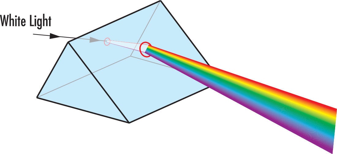
Figure 1: Dispersion through a Prism
A notable characteristic of prisms is their ability to be modeled as a system of plane mirrors in order to simulate the reflection of light within the prism medium. Replacing mirror assemblies is perhaps the most useful application of prisms, since they both bend or fold light and change image parity. Often, multiple mirrors are needed to achieve results similar to a single prism. Therefore, the substitution of one prism in lieu of several mirrors reduces potential alignment errors, increasing accuracy and minimizing the size and complexity of a system.
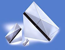
PRISM MANUFACTURING
Before delving into the theory behind prisms, consider their manufacturing process. In order to be used successfully in most applications, prisms must be manufactured with very strict tolerances and accuracies. Due to the variability in shape, size, and, most importantly, the number of surfaces, a large-scale automated process for prism manufacturing is quite infeasible. In addition, most high precision prisms tend to be made in low quantities, meaning an automated process would be unnecessary.
First, a block of glass (known as a "blank") of a specified grade and glass type is obtained. This block is then ground, or generated, by a metal diamond bonded wheel into a near-finished product. A majority of the glass is removed quickly in this stage resulting in flat, but still coarse surfaces (Figure 2a). At this point, the dimensions of the prism-to-be are very close to the desired specifications. Next is a fine grinding process that removes sub-surface breaks from the surface; this stage is known as smoothening. Scratches left from the first stage are removed in the second stage (Figure 2b). After smoothening, the glass surfaces should appear cloudy and opaque. In both the first two stages, the prism surface must be wet in order to expedite glass removal and prevent overheating of the glass itself.
The third stage involves polishing the prism to the correctly specified surface flatness. In this stage, the glass is rubbed against a polyurethane polisher wet with "slurry," an optical polishing compound typically comprised of water mixed with pumice or cerium oxide (Figure 2c). The exact duration of the polishing stage is highly dependent on the surface specifications required. Once polishing is completed, chamfering can begin. In this fourth stage, the edges of the prism are subjected to a spinning diamond plate in order to slightly dull the sharp edges it obtains throughout the aforementioned steps (Figure 2d). After chamfering, the finished prism is cleaned, inspected (via both manual and automated means), and coated with anti-reflection (AR) and/or metallic mirror coatings, if necessary, to further aid in overall transmission and/or reflection. Though the process is much more involved and may require more iterations or operations due to the number of surfaces on a prism, the Generating, Smoothening, Polishing and Chamfering Stages are roughly outlined in Figures 2a - 2d.

Figure 2a: Prism Manufacturing Process: Generating Stage
Figure 2b: Prism Manufacturing Process: Smoothening Stage
Figure 2c: Prism Manufacturing Process: Polishing Stage
Figure 2d: Prism Manufacturing Process: Chamfering Stage
Throughout the manufacturing of a prism, it is necessary to continually adjust and secure each surface being worked on. Securing a prism in place involves one of two methods: blocking and contacting. Blocking entails arranging the prism in a metal tool with hot wax. Contacting, on the other hand, is an optical bonding process done at room temperature where two clean glass surfaces are fastened together simply through their Van Der Waals interaction. Contacting is utilized if high precision tolerances are required because it does not require additional adjustments to be made during the Generating, Smoothening, or Polishing Stages to account for the wax thickness between the prism surface and the contact block.
During every stage of the prism manufacturing process, from generating to blocking and contacting, a skilled optician is required to manually inspect and adjust the prism surfaces being worked on. As a result, it is extremely labor intensive and requires experience and skill in order to complete. The entire process often requires a significant amount of time, work, and concentration.
THEORY: LIGHT AND REFRACTION
Understanding how a prism works is key to deciding which type of prism fits best for a specific application. In order to do so, it is important to first understand how light interacts with an optical surface. This interaction is described by Snell's Law of Refraction:
Where $ \small{n_1} $ is the index of the incident medium, $ \small{\theta_1} $ is the angle of the incident ray, $ \small{n_2} $ is the index of the refracted/reflected medium, and $ \small{\theta_2} $ is the angle of the refracted/reflected ray. Snell's Law describes the relationship between the angles of incidence and transmission when a ray travels between multiple media (Figure 3).
Figure 3: Snell's Law and Total Internal Reflection
A prism is notable for its ability to reflect the ray path without the need for a special coating, such as that required when using a mirror. This is achieved through a phenomenon known as total internal reflection (TIR). TIR occurs when the incident angle (angle of the incident ray measured from normal) is higher than the critical angle $ \small{\theta_c} $:
Where $ \small{n_1} $ is the index of refraction for the medium where the ray originates, and $ \small{n_2} $ is the index of refraction for the medium where the ray exits. It is important to note that TIR only occurs when light travels from a high index medium to a low index medium.
At the critical angle, the angle of refraction is equal to 90°. Referencing Figure 3, notice that TIR occurs only if $ \small{\theta} $ exceeds the critical angle. If the angle is below the critical angle, then transmission will occur along with reflection as given by Snell's Law. If a prism face does not meet TIR specifications for the desired angle(s), then a reflective coating must be used. This is why some applications require coated versions of a prism that would otherwise work well uncoated in another application.
THEORY: IMAGE HANDEDNESS/PARITY
A significant aspect of imaging through a prism is image handedness (parity), otherwise referred to as the orientation of the image. This is introduced every time the ray path hits a plane mirror, any flat reflective surface, or a prism surface at an angle that produces TIR. There are two types of handedness: right and left. Right-handedness (Figure 4) describes the case where an image undergoes an even number of reflections, resulting in the ability to read it clearly (assuming the image is text) in at least one position. Left-handedness (Figure 5) describes the case where the image undergoes an odd number of reflections, leading to an irregularity in the position of the image that is comparable to what one sees in a mirror.

Figure 4: Right Handedness or Even Parity

Figure 5: Left Handedness or Odd Parity
In addition to parity, there are three types of image change (Figure 6). An inversion is an image-flip over a horizontal axis, whereas a reversion is an image-flip over a vertical axis. When both are done at the same time, an image rotation of 180° occurs and there is no change in parity. Another way to think of parity is defining it as being determined by looking back against the propagation direction towards either the object or image in its optical space (Figure 7).
Figure 6: Inversion (Top), Reversion (Middle), and Rotation (Bottom)

Figure 7: How Parity is Determined
When using a prism, consider the following four points:
- Image Handedness Changes Every Time an Image is Reflected.
- Any Point along the Plane of the Reflecting Surface is Equidistant from the Object and Its Image.
- Snell's Law Can Be Applied to All Surfaces.
- When Testing for Image Handedness/Parity, It is Best to Use a Non-Symmetrical Letter Such as R, F, or Q. Avoid Using Letters Like X, O, A, etc.
WHAT IS PYRAMID TOLERANCE?
Some prisms, like right angle and roof prisms, often have a specified pyramid tolerance or allowable pyramid error. This is not one of the physical angles of the prism, but rather a way to describe the accuracy of parallel surfaces of the prism with respect to each other. If all the surfaces are extended in a perfect prism, the same shape would continue forever. This would be a pyramid error of zero. In reality, there will be some small level of misalignment in parallel prism surfaces, which when extending the surfaces of the prism would eventually come to a point to form a pyramid. The angle at the peak of this theoretical pyramid is the pyramid error. This is calculated from a projection of one edge of the prism to the line that is between the edges on the opposite face of the prism.
Typical pyramid tolerances for precision quality prisms are from 1-3 arcminutes. Commercial quality prisms often have tolerances in the 5-10 arcmin range. Pyramid tolerance is essentially a tilt tolerance on the surfaces perpendicular to the triangles of a triangular prism. Typically, the way prisms bend light is considered in a 2-dimensional plane (X-Z). The tilt from a pyramid tolerance will be perpendicular to this in the Y plane. For many systems, pyramid error has little-to-no effect on performance and can be adjusted out with a tilt of the prism. But this specification can be important in some applications where the tilt in Y cannot be mechanically tilted to compensate for this error. For those applications, pyramid tolerances must be tightly controlled. This can be especially problematic in roof prisms.
TYPES OF PRISMS
There are four main types of prisms: dispersion prisms, deviation, or reflection prisms, rotation prisms, and displacement prisms. Deviation, displacement, and rotation prisms are common in imaging applications; dispersion prisms are strictly made for dispersing light, therefore not suitable for any application requiring quality images.
Dispersion Prisms
Prism dispersion is dependent upon the geometry of the prism and its index dispersion curve, based on the wavelength and index of refraction of the prism substrate. The angle of minimum deviation dictates the smallest angle between the incident ray and the transmitted rays (Figure 8). The green wavelength of light deviates more than red, and blue more than both red and green; red is commonly defined as 656.3nm, green as 587.6nm, and blue as 486.1nm.
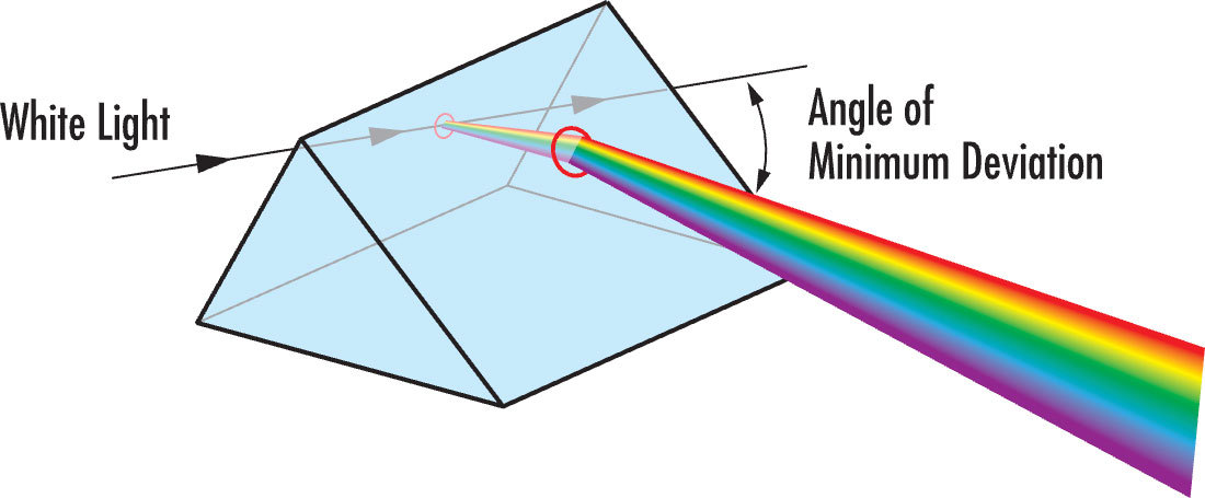
Figure 8: Dispersion through a Prism
Deviation Prisms
Prisms that deviate the ray path, rotate the image, or simply displace the image from its original axis are helpful in many imaging systems. Ray deviations are usually done at angles of 45°, 60°, 90°, and 180°. This helps to condense system size or adjust the ray path without affecting the rest of the system setup.
Rotation Prisms
Rotation prisms, such as dove prisms, are used to rotate an image after it is inverted.
Displacement Prisms
Displacement prisms maintain the direction of the ray path, yet adjust its relation to the normal.
Prism Selection Guide
To aid in selecting the best prisms for specific applications, consider the following selection guide of the most commonly used in the optics, imaging, and photonics industries.
|
Prism Selection Guide
|
|
Equilateral Prisms - Dispersion
|
 Function Function
 |
|
Littrow Prisms - Dispersion, Deviation
|
 Function Function
 |
|
Right Angle Prisms - Deviation, Displacement
|
 Function Function
 |
|
Penta Prisms - Deviation
|
 Function Function
 |
|
Half-Penta Prisms - Deviation
|
 Function Function
 |
|
Amici Roof Prism - Deviation
|
 Function Function
 |
|
Schmidt Prisms - Deviation
|
 Function Function
 |
|
Retroreflectors (Trihedral Prisms) - Deviation, Displacement
|
 Function Function
 |
|
Wedge Prisms - Deviation, Rotation
|
 Function Function
 |
|
Rhomboid Prisms - Displacement
|
 Function Function
 |
|
Dove Prisms - Rotation
|
 Function Function
 |
|
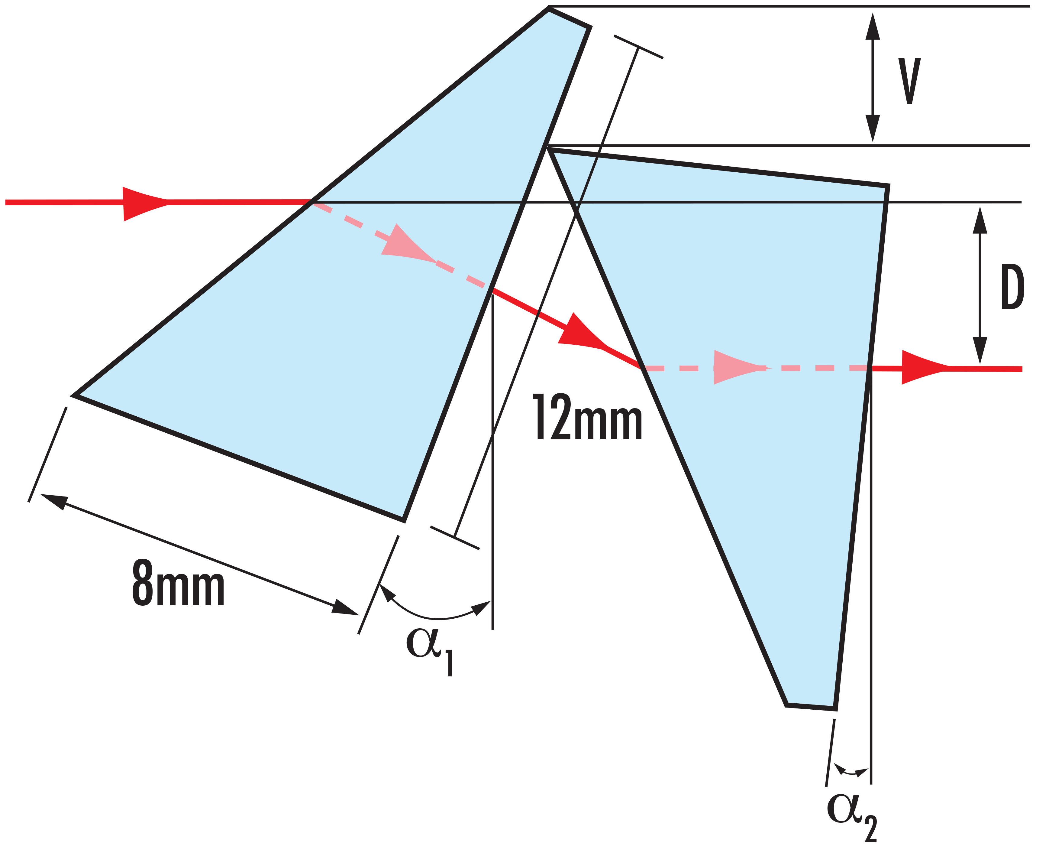
Anamorphic Prism Pairs - Expansion
|
 Function Function
 |
|
Light Pipe Homogenizing Rods - Homogenation
|
 Function Function
 |
|
Tapered Light Pipe Homogenizing Rods - Homogenation
|
 Function Function
 |
This introduction gave a look into the manufacturing process and the theory associated with prisms, as well as a selection to help you find the best prism for your application. To learn some examples of prism applications, view Optical Prism Application Examples.


もしくは 現地オフィス一覧をご覧ください
クイック見積りツール
商品コードを入力して開始しましょう
Copyright 2023, エドモンド・オプティクス・ジャパン株式会社
[東京オフィス] 〒113-0021 東京都文京区本駒込2-29-24 パシフィックスクエア千石 4F
[秋田工場] 〒012-0801 秋田県湯沢市岩崎字壇ノ上3番地
The FUTURE Depends On Optics®