製品がカートに追加されました
TECHSPEC® components are designed, specified, or manufactured by Edmund Optics. TECHSPEC® ブランドの製品は、エドモンド・オプティクスによってデザイン、規格化、あるいは製造されます。もっと詳しく

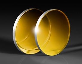
Beamsplitter Compensation Plate, Fused Silica, 25mm Dia, NIR

ビームスプリッター用補償板

×
商品コード #89-929 New 8 個 在庫有
Quantity Selector - Use the plus and minus buttons to adjust the quantity. +
¥27,300
在庫数は海外倉庫分の在庫も含んでおり、日本国内の在庫を示すものではありません。詳細な在庫状況は、カートに追加してご確認ください。
購入数量別価格
数量 1-10 ¥27,300 単価
数量 11-25 ¥21,850 単価
それ以上? 見積依頼する
製品ダウンロード

仕様

物理的および機械的特性

面取り:
Protective as needed
有効径 CA (%):
90
有効径 CA (mm):
22.50
直径 (mm):
25.00 +0.00/-0.10
端面:
Fine Ground
全厚 (mm):
3.00 ±0.20
ウェッジ角度 (分):
30 ±1

光学的特性

入射角 (°):
45
コーティング:
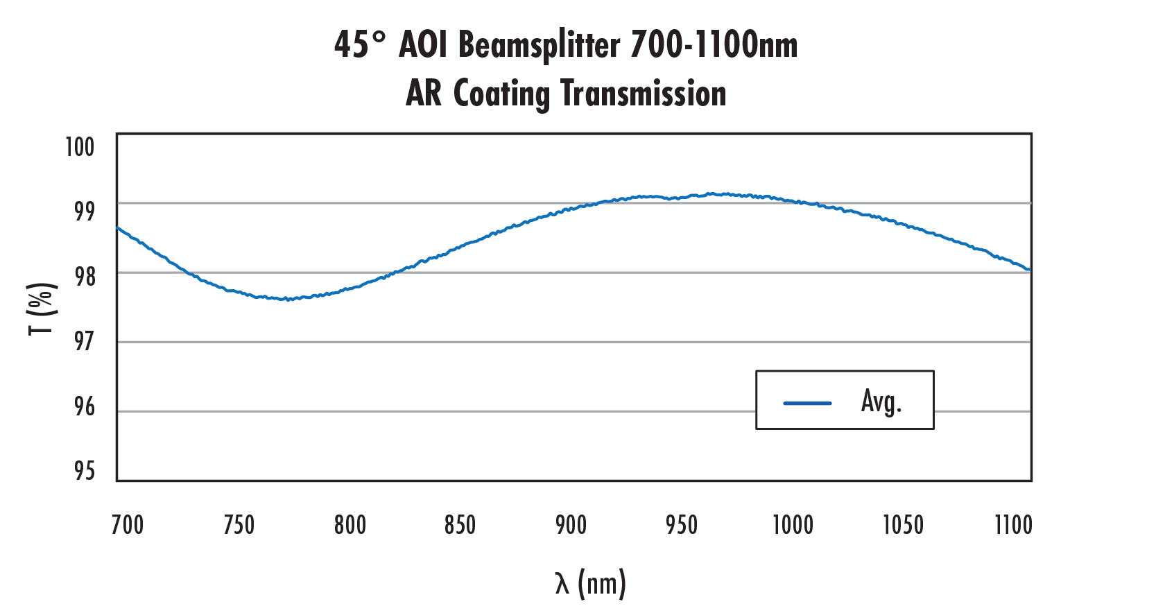
45 ° AOI BBAR (700-1100nm)
コーティングスペック:
S1 & S2: Rabs ≤ 2.0% from 700-1100nm @ 45° AOI
Ravg ≤ 1.0% from 700-1100nm @ 45° AOI
基板: 多くの光学ガラスメーカーが、殆ど等しい光学特性を持ったガラスを独自の呼称で製造・販売しています。詳細はこちら
Fused Silica (Corning 7980)
平面度 (P-V):
λ/10 @ 632.8nm
表面品質 (キズ-ブツ):
20-10
波長範囲 (nm):
700 - 1100

法規制対応状況

RoHS 2015/863:
適合証明書:
Reach 253:

商品詳細

TECHSPEC® ビームスプリッター用補償板は、プレート型ビームスプリッターを45°入射で用いるシステムでの光路長を等しくするためにデザインされています。精密な合成石英から作られるこのウインドウは、透過ビームと反射ビームの両方が同じ材料厚を通るようにして、位相の完全性と波面品質を維持します。TECHSPEC λ/10 プレート型ビームスプリッターと対で用いることで、補償板は要求の厳しい光学システムにおいて分散を最小化し、高い干渉コントラストを維持します。TECHSPEC ビームスプリッター用補償板は、内部干渉と戻り反射を最小化する30分のウェッジ付きで、精密アプリケーションに向けた格好の選択になります。この補償プレートは、正確なビームパスマッチングを必要とする干渉、計測、および分光アプリケーションに最適です。

ビームスプリッターをマイケルソン干渉計やその他の干渉計に用いる時、その厚さによって光路長や分散にわずかな差を引き起こします。補償プレートは、この差を補正することができ、広帯域システムにおいて特に有効です。補償板を選定する際は、使用するビームスプリッターと同じ基板や厚さのものを用いて、光路長を正しく調整する必要があります。
技術情報

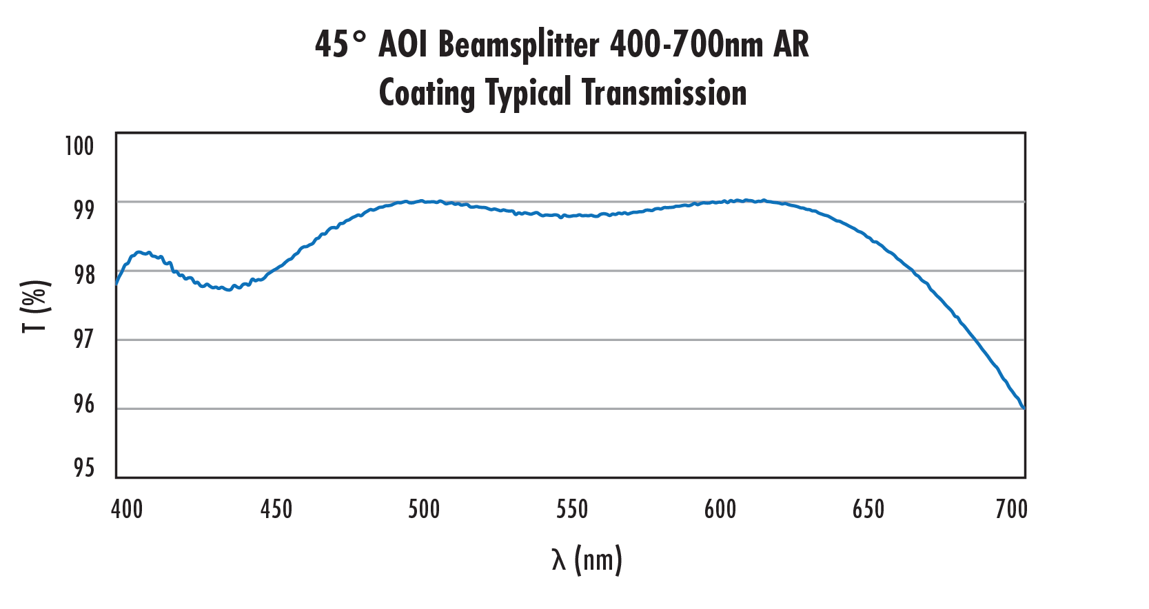
Graph showing typical transmission percentage of 45° AOI beamsplitter with 400-700nm AR coating across wavelength range
Transmission percentage chart of 45° AOI beamsplitter with AR coating from 700 to 1100 nm wavelength
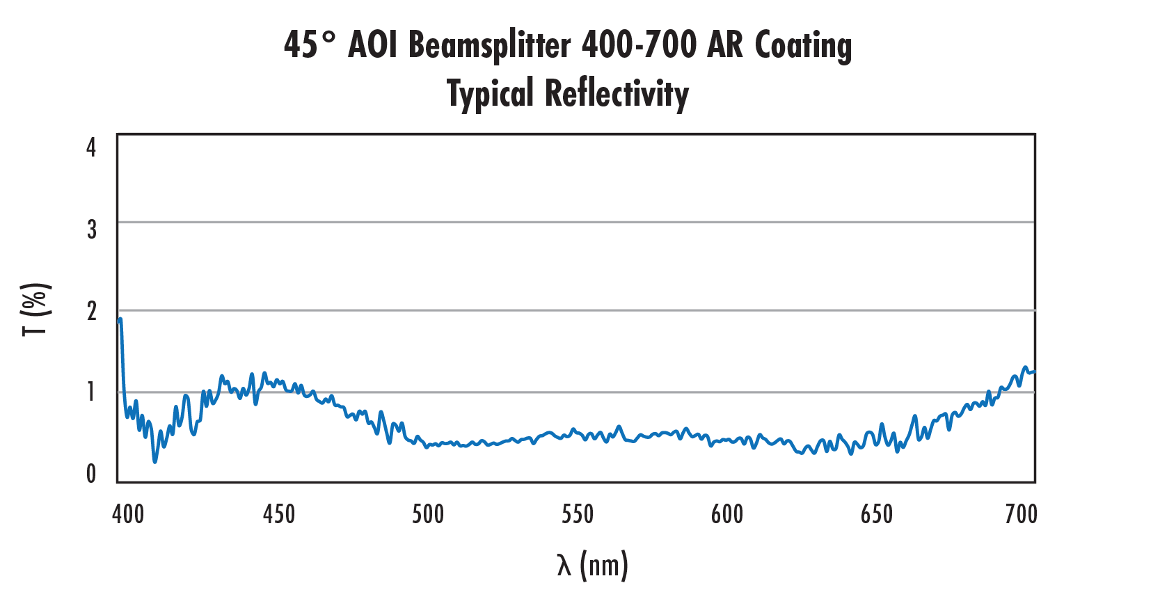
Reflectivity chart showing typical reflectivity of 45° AOI beamsplitter with 400-700 nm AR coating across wavelength range
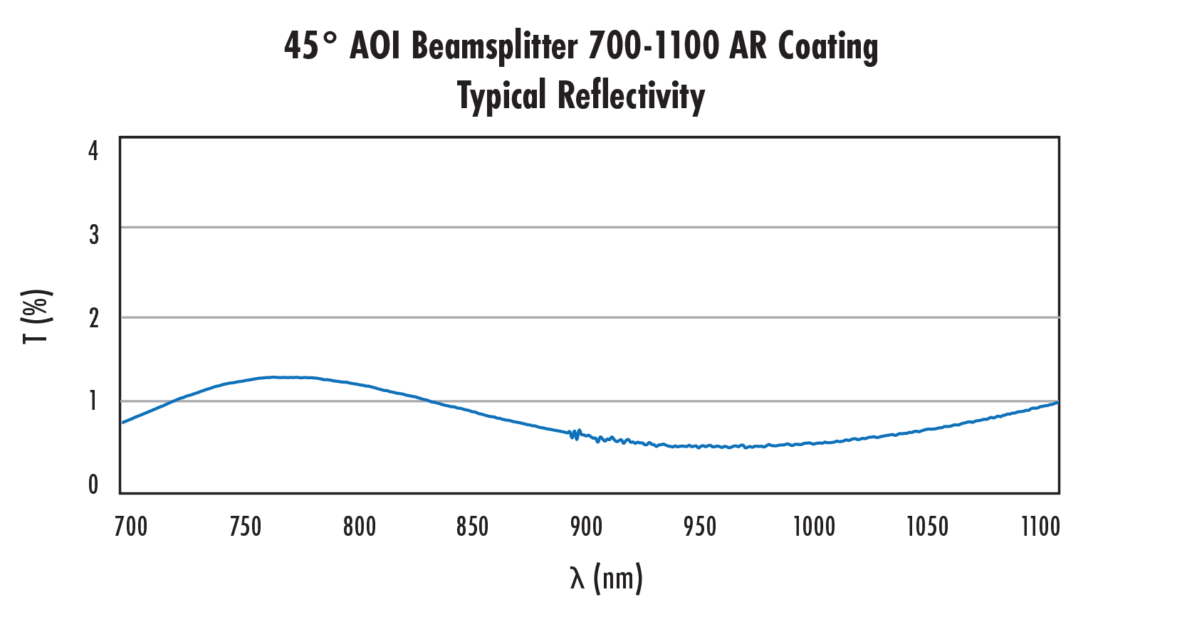
Reflectivity curve of 45° AOI beamsplitter with 700-1100 nm AR coating showing typical reflectivity percentage
Beamsplitter Compensator Plates
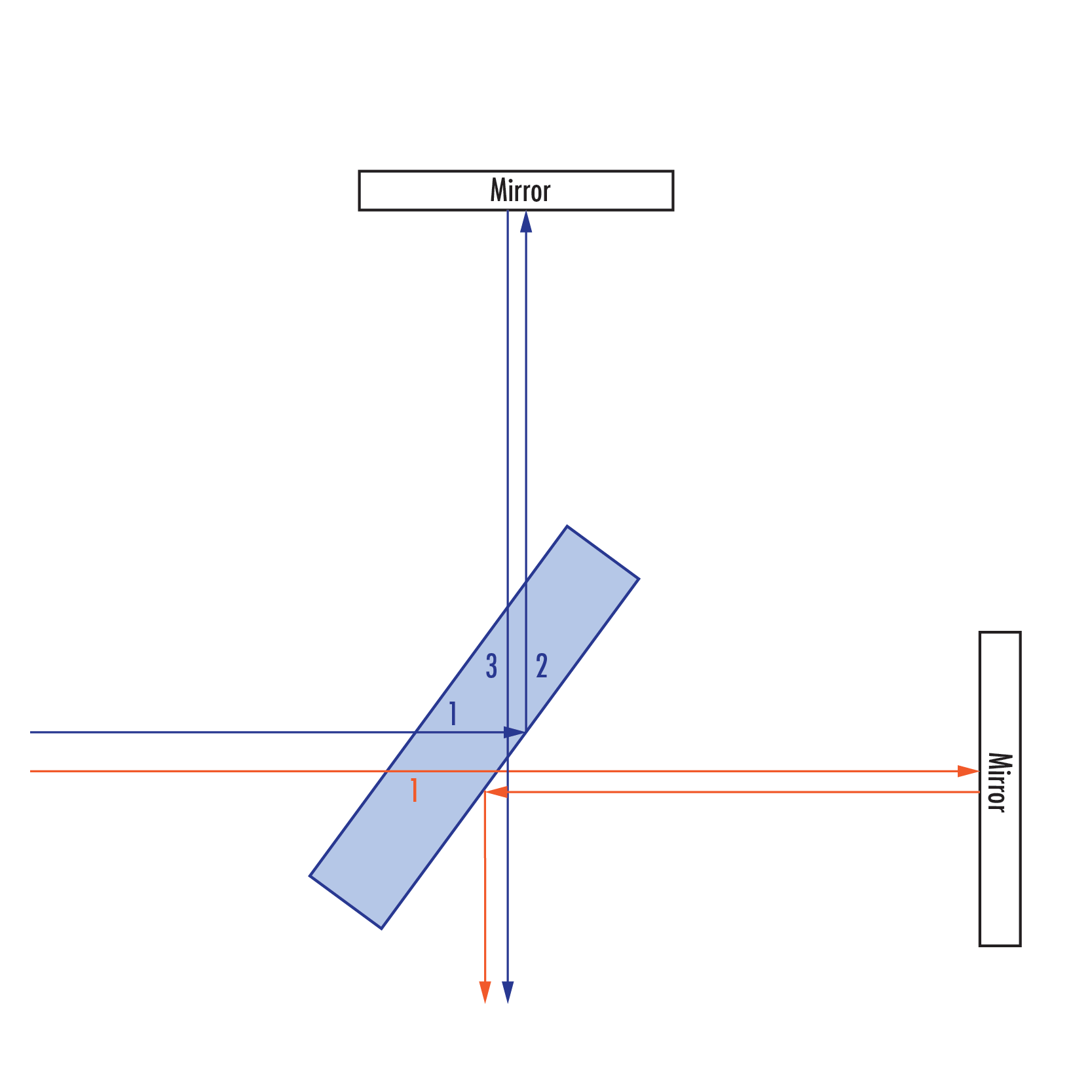
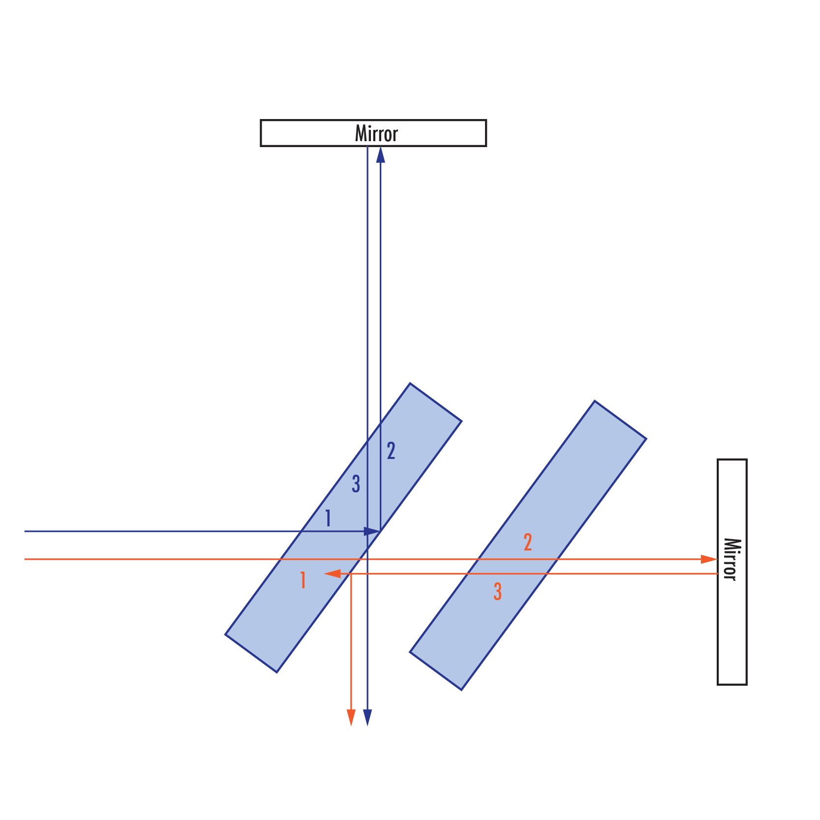
Diagram showing beam path in an uncompensated interferometer setup. (Please note, reflected beams are depicted offset for demonstrative purposes).  Numbers refer to number of passes through the beamsplitter substrate. The blue beam (initially reflected at the beamsplitter) travels through the beamsplitter substrate three times, while the orange beam (initially transmitted through the beamsplitter) travels through the beamsplitter only once. This results in a differing path length and dispersion between the two beams once they arrive at the sensor.
Diagram showing beam path in an uncompensated interferometer setup. (Please note, reflected beams are depicted offset for demonstrative purposes). Numbers refer to number of passes through the beamsplitter substrate. The blue beam (initially reflected at the beamsplitter) travels through the beamsplitter substrate three times, while the orange beam (initially transmitted through the beamsplitter) travels through the beamsplitter only once. This results in a differing path length and dispersion between the two beams once they arrive at the sensor.
With the addition of a compensator plate of the same thickness and refractive index of the beamsplitter, the orange beam now experiences the same change in path length and dispersion as does the blue beam.

コーティング曲線

 
販売や技術サポート
 
もしくは 現地オフィス一覧をご覧ください
簡単便利な
クイック見積りツール
商品コードを入力して開始しましょう