


Assembling Compact Machine Vision Microscopy Systems with 120i Plan APO Infinity Corrected Objectives
著者: Rebecca Charboneau
TECHSPEC® 120i Plan APO Infinity Corrected Objectives are machine vision infinite conjugate microscope objectives designed to reduce the overall size and weight of an imaging system while not compromising optical performance. Because the objectives do not need to be parfocal to each other, the overall system length is reduced. This means that the objectives do not focus images in the same plane, thus eliminating the need for a microscope turret. The TECHSPEC 120i Plan APO Infinity Corrected Objectives feature C-Mount threading allowing for easy integration with industrial C-Mount cameras. These objectives are ideal for biomedical and machine vision applications such as microscopy, flow cytometry, and pharmaceutical or assembly line inspection. This application note will review the correct way to assemble the TECHSPEC 120i Plan APO Infinity Corrected Objectives and accessories for a machine vision imaging system.
Assembling a Basic Digital Microscope System
The minimum required components for digital microscope system are the 5X, 10X, or 20X TECHSPEC® 120i Plan APO Infinity Corrected Objectives (#15-941, #15-943, or #15-944), camera tube (#18-504), tube lens (#18-505), lens tube spacer (#18-506), and an industrial C-Mount camera (Figure 1). These components can be configured for vertical or horizontal mounting depending on the sample under inspection. For biomedical applications, typically mounting in a vertical position is most effective as biological samples are often submerged in an aqueous medium.

Figure 1: Basic Imaging System with TECHSPEC® 120i Plan APO Infinity Corrected Objectives
To properly assemble this basic digital microscope with the TECHSPEC® 120i Plan APO Infinity Corrected Objectives, a 3mm metric (M3) hex key is needed to tighten the setscrews on the tube lens spacer assembly (#18-506) to the dovetail side of the tube lens assembly (#18-505). A full schematic of this setup with threading details can be seen in Figure 5 below. The tube lens spacer assembly has a retainer ring that can be removed to reveal M29 threading for compatibility with Edmund Optics’ thin and thick 25/25.4mm single optic mount. This M29 threading on the tube lens spacer allows for other optical components such as filters to be easily mounted in the imaging system. Table 1 below provides the full list of components for this basic digital microscope.
| Table 1: Sample Stock No. for Basic Imaging System with TECHSPEC® 120i Plan APO Infinity Corrected Objectives | |
|---|---|
| Stock No. | Description |
| #15-941, #15-943, #15-944 | TECHSPEC® 120i Plan APO Infinity Corrected Objectives |
| #18-504 | Camera Tube |
| #18-505 | Tube Lens Assembly |
| #18-506 | Tube Lens Spacer Assembly |
Assembling a Fluorescence Microscope System
For life science applications that require a basic fluorescence microscopy setup, the TECHSPEC® 120i Plan APO Infinity Corrected Objectives have the proper accessories to mount TECHSPEC Fluorescence Filter Sets. The fluorescence imaging setup uses the same camera tube (#18-504") and tube lens assembly (#18-505) to thread onto an industrial C-mount camera. Instead of the tube lens spacer assembly, the filter cube assembly (#18-508) is fastened to the dovetail side of the tube lens assembly with a M3 hex key. A TECHSPEC® 120i Plan APO Infinity Corrected Objective is then threaded directly into the filter cube assembly to complete this setup (Figure 2).
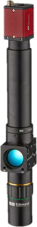
Figure 2: Fluorescence Imaging System with TECHSPEC® 120i Plan APO Infinity Corrected Objectives
The filter cube assembly (#18-508) holds one set of fluorescence filters: an excitation filter, an emission filter, and a dichroic filter. The filter cube accepts TECHSPEC Fluorescence Filter Sets that are compatible common fluorophores such as DAPI, GFP and ICG. The filter cube assembly mounts 25mm and 25.4mm diameter bandpass filters and 25.2 x 35.6mm dichroic filters. The excitation and emission filters are easily secured into the assembly with M29 retainer rings that can be removed using a spanner wrench. Figure 3a below shows the correct placement of the excitation and emission filters based on the illumination source and sample. To insert the dichroic filter, the filter cube assembly must be separated into two halves using a M2.5 hex key. The dichroic filter is placed at a 45° angle of incidence in the filter cube with the beamsplitter coating facing down (i.e. facing the sample) as shown in Figure 3b. Once the dichroic filter is secured in place, the halves of the cube should be aligned before tightening the set screws in place (Figure 3c). The dichroic filter should be visible through the side opposite of the emission filter once fully assembled (Figure 3d). For mounting flexibility, the filter cube assembly has ¼-20”, M6, and M4 post threads for mounting. The full list of parts required for this setup can be referenced in Table 2 below.
a.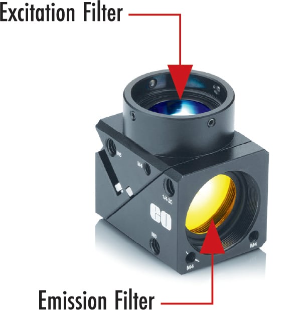 |
b.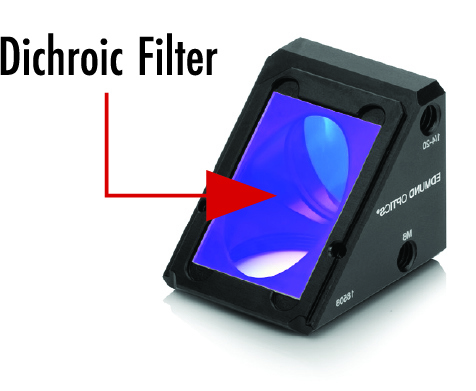 |
c.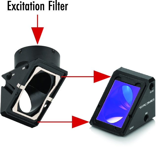 |
d.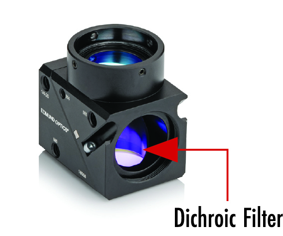 |
Figure 3: Filter Cube Setup
| Table 2: Sample Stock No. for Fluorescent Imaging System with TECHSPEC® 120i Plan APO Infinity Corrected Objectives | |
|---|---|
| Stock No. | Description |
| #15-941, #15-943, #15-944 | TECHSPEC® 120i Plan APO Infinity Corrected Objectives |
| #18-504 | Camera Tube |
| #18-505 | Tube Lens Assembly |
| #18-508 | Filter Cube Assembly |
| #18-509 | 0.312” Fiber Adapter Assembly |
| Family ID #3226 | Fluorescence Filter Kits |
When using the fluorescence imaging setup, a light source can be adapted directly to the filter cube assembly (#18-508) with the 0.312” fiber adapter assembly (#18-509). This fiber adapter connects to coaxial light sources that are compatible with 8mm or ¼” (0.312”) fiber illumination ports to be used as the excitation source (Figure 4). Edmund Optics has a variety of compatible light sources found here.
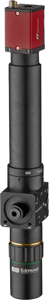
Figure 4: Fluorescence Imaging System with TECHSPEC® 120i Plan APO Infinity Corrected Objectives & Fiber Adapter
Additional accessories that may be used with these systems can be found in Table 3 below. The M29 tube mount assembly (#18-510) can be used to mount the digital microscope to a post to relieve tension from the camera. The M29 tube mount assembly has ¼-20”, M6, and M4 post threads for easy integration with optical posts. The M29-to-30mm dovetail adapter (#18-507) or C-thread to dovetail adapter (#18-511) are used to allow for a quick change of threading for C-mount and M29 systems. This provides users flexibility to configure their own setups with the TECHSPEC® 120i Plan APO Infinity Corrected Objectives. For example, these accessories can be used to configure the digital microscope setup into an existing imaging system such as Edmund Optics’ Multi-Element Tube System.
| Table 3: Additional Accessories for the TECHSPEC 120i Plan APO Infinity Corrected Objectives | |
|---|---|
| Stock No. | Description |
| #18-510 | M29 Tube Mount Assembly |
| #18-511 | C-mount to Dovetail Adapter |
| #18-507 | M29 to 30mm Dovetail Adapter |
When determining what digital microscope setup is ideal, consider using the TECHSPEC® 120i Plan APO Infinity Corrected Objectives for a more compact system that does not compromise optical performance. Using the TECHSPEC® 120i Plan APO Infinity Corrected Objectives allows for customization with different options for mounting or the addition of fluorescence filters, making them easy to integrate into a machine vision or biomedical application.

Figure 5: 120i Plan APO Objective Setup Schematic
Additional Resources
- Understanding Microscopes and Objectives
- Digital Video Microscope Objective Setups
- Optical Microscopy Application: Fluorescence
- Infinite Conjugate Tube Length Calculator
- Fluorophores and Optical Filters for Fluorescence Microscopy
- Cameras
- 6 Considerations for Medical Optical Device Development Webinar Recording
- Optics Enabling Life Sciences and Medical Devices
もしくは 現地オフィス一覧をご覧ください
クイック見積りツール
商品コードを入力して開始しましょう
Copyright 2023, エドモンド・オプティクス・ジャパン株式会社
[東京オフィス] 〒113-0021 東京都文京区本駒込2-29-24 パシフィックスクエア千石 4F
[秋田工場] 〒012-0801 秋田県湯沢市岩崎字壇ノ上3番地
The FUTURE Depends On Optics®